|
|
|
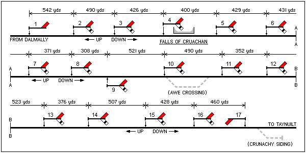
Figure 1 (below) shows the layout of semaphore signals forming part of an unusual installation that is still operational on the Oban line in the West Highlands of Scotland.
|
| Fig. 1: Layout of Signals in the Pass of Brander. |
|---|
Between Dalmally and Taynuilt, the railway follows the northern shore of Loch Awe for a distance of seven miles (11.2 km). The loch narrows to the west, where it enters the Pass of Brander. Ben Cruachan lies to the north, its slopes steeply rising to a summit more than 1,000 metres above the track. Falling rocks in the Pass of Brander had been a cause for concern since the opening of the railway on 1 July 1880. The secretary of the Callander & Oban Railway, John Anderson, devised a warning system to help protect the line against the threat of boulders falling from the mountainside and causing a derailment. This took the form of a tensioned wire screen, which would automatically trigger signals in both directions to 'danger' if broken.
The screen presently runs for a distance of 4 miles and 14 yards (6,450 metres) along the north side of the railway. It comprises ten single-strand mild steel wires supported by steel posts generally spaced between 9 and 12 feet apart. The wire currently used is 17 SWG, although some older and heavier wire (15 SWG) remains in use. The wires are spaced at either 9 or 10 inches apart, depending upon the age of post that supports them (9 inches in the case of the newer posts).
The screen is positioned in such a way that if a falling stone was to clear the highest wire, it should not hit the track but would continue downwards, possibly to land on the adjacent road or in the loch below. In some places, where there appeared to be a danger that boulders might bounce over the screen and onto the track, the height of the screen was increased to twelve or fourteen wires. This was achieved by replacing a length of wire with a wire loop connected at each end by a pulley. These additional wires have now been removed, but the taller posts that once supported them can still be seen in places. Where the screen crosses over a stream, the gap between the ground and the bottom wire might be sufficiently wide that a large boulder could roll under the screen without striking it. At these places, the gap is filled by a 'basket' of strong wire attached to the lower screen wires. In the event of a heavy stone falling into the basket, the screen wires will break.
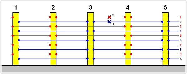
Lever posts are situated at each end of the screen and at intervals of approximately a quarter mile (0.4 km). Originally these posts were made of lattice steel, but most have now been replaced with timber (comprising two 15-foot timbers through-bolted back to back). Each alternate wire passes the first lever post and is connected with the next one (this is represented diagrammatically in figure 2). Each lever post stands opposite a signal post to which it is connected by wires that pass overhead.
|
| Fig. 2: Arrangement of Wires in Boulder Screen. |
|---|
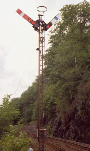
The signal posts, which are numbered 1 to 17 from east to west, stand on the south or loch side of the line, except for number 9, which is on the north or hill side. Signal 1 carries only a Down direction arm and signal 17 only an Up direction arm. The other fifteen signals each carry both an Up and a Down arm, fixed at the same height on the post (approximately 24 feet above rail level). Ordinary upper quadrant stop arms are fitted, although drivers are permitted to pass a stone signal at 'danger' with caution. Distant signals are not provided.
|
| Fig. 3: Stone Signal No. 8. |
|---|
|
||||||||||||||||||||||||||||||||||||||||||||||||||||||||||||||||||||||||
| Table 1: Details of Signals. |
|---|
So long as the wires in the screen remain intact, the signal arms stay in the 'clear' position. In the event of a single wire being broken by a stone, one Up arm and one Down arm are placed at 'danger'. Which particular signals are affected depends on which individual wire was broken. If a break occurred between lever posts 3 and 4, for example, the result would be that either:
With reference to figure 2, a broken wire at "A" (or any red coloured wire between lever posts 3 and 4) will affect signals 2 and 4, while a break at "B" (or any blue coloured wire between lever posts 3 and 4) will affect signals 3 and 5. If two or more adjacent wires break, all four arms mentioned above would go to 'danger'.
It can be seen that a driver running in one direction could find a signal showing 'clear' after having passed one at 'danger' but before the potential obstruction is encountered. Because of this, drivers are instructed that, having sighted one of the signals at 'danger', they must reduce speed and proceed with caution until a second 'clear' signal is reached or until the last stone signal is passed. They must also inform the signalman at Banavie Signalling Centre by radio that one of the stone signals is at 'danger'. In former times when two men travelled together in the cab, the driver was instructed to stop and send his assistant ahead on foot to see that the line was clear of boulders.
|
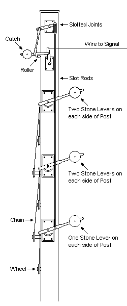
| Fig. 4: Side view of Lever Post. |
|---|
Every wire in the screen is connected at each end (via an adjuster and a short length of chain) to a weighted 'stone lever' on a lever post. If a wire breaks, the tension in it is lost and both levers drop. Each lever post carries ten of these stone levers, arranged five on each side. Both sides of the lever post are identical in operation and work independently of each other. The following description concerns the operation of one side, as shown in figure 4.
The signal arm is held in the 'clear' position by a weighted catch, which rests on a roller fixed to the back of the lever post. The catch is linked to a straight crank at the top of the post. The front end of this crank has a stud, which projects through slots in the uppermost ends of the five vertical 'slot rods', each rod being directly linked to a stone lever. Any stone lever falling will therefore operate the crank, the stud being free to move through the slots in the other four rods. Operation of the crank lifts the catch off its roller and slackens the wire to the signal arm, so that it falls by gravity to the 'danger' position.
To restore a signal to 'clear', it is first necessary to repair any broken screen wires. Before a repair is made, the stone levers at either end of the broken wire are tied in the raised position. When all five levers on one side of a lever post are raised, the signal may be returned to 'clear'. The signal arm is held or tied in the 'off' position to slacken the wire from the lever post before the half bar is pulled back to re-engage the catch on the roller. Lastly, the signal arm and stone lever are untied.
At the extremities of the screen, each of the ten wires is connected to a stone lever on the same lever post. The two wires that cross from the lever post to the signal connect with an ordinary drop-off slot fitted to the signal post so that the slackening of either wire will place the signal arm to 'danger'. At signal 17, however, one side of the lever post is not now operational. As a result, only one wire runs between the lever post and signal, and there is no slot on the signal post.
The original boulder screen came into use in January 1882, just eighteen months after the railway's opening. It was 1,112 yards (1,017 metres) in length and had four associated semaphore signals. At that time, the screen covered the section of line between the present stone signals numbered 6 and 9.
In August 1882, a decision was made to extend the screen at both ends. The extensions, 2,285 yards (2,089 metres) eastwards and 2,262 yards (2,068 metres) to the west, came into use on 17 April 1883. These increased the overall length of the screen to 5,659 yards (5,174 metres), covering the line between the present stone signals numbered 1 and 14.
The signalling in the Pass of Brander was further complicated by the provision of a signal box and crossing loop between stone signals 10 and 11, to split the single line section between Loch Awe and Taynuilt. Awe Crossing, as it was known, opened on 29 July 1893. The Down and Up Distant signals were carried on, and slotted by, stone signals numbers 9 and 12, respectively. Stone signal number 10 was repositioned 48 yards (44 metres) further west and provided with an additional Down direction arm lower down the post, this being Awe Crossing's Down Home signal. This arm was removed on 10 August 1893, and thereafter the remaining arm acted both as the Down Home and the automatic stone signal. This arrangement is shown in figure 5.
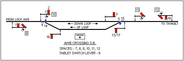
|
| Fig. 5: Awe Crossing Signalling Diagram. |
|---|
In 1895, the stone signals were fitted with commutators, which operated electric alarm bells in the event of a rockfall. There were two separate circuits; one to the east of Awe Crossing and one to the west. Both circuits controlled bells in the signal box and signal watchman's house at Awe Crossing. In addition, the east and west circuits controlled bells in the foremen platelayers' houses at Falls of Cruachan and Bridge of Awe, respectively. When Awe Crossing signal box was abolished on 2 October 1966 (together with the next box to the east, Loch Awe), the bells were transferred to Dalmally and Taynuilt boxes. The commutators were removed when Radio Electronic Token Block (RETB) was commissioned in 1988.
Stone signals 15, 16 and 17 were brought into use on 30 September 1913, the screen having been extended by 1,395 yards (1,276 metres) at the west end, bringing its total length to the present 7,054 yards (6,450 metres).
The signals had originally been fitted with lower quadrant semaphore arms. As an economy measure, those that carried both Up and Down direction arms had only a single lamp, which shone in both directions. For this reason, the arm on one side of the post was of the unusual left-hand spectacle type. The signals were converted to upper quadrant type around 1968 and are now electrically lit. From late 1996, highly reflective paint was applied to the signal arms, greatly improving their visibility in darkness. Railings for the safety of maintenance staff were subsequently erected around the lever posts, and in late 2003, steps were provided from the trackside leading up to each of the lever posts. Many of the steel posts that support the screen wires were replaced in 2012/2013.
The Pass of Brander signals were not unique, because another part of the Callander & Oban Railway had once been protected by stone signals. These were at Craig-na-Cailleach on the west side of Loch Lubnaig, about six miles (9.6 km) from Callander. The boulder screen there was just 405 yards (370 metres) long, with one signal at each end, all situated on the west side of the railway. They came into use on 23 August 1892 following a rockfall and lasted until the closure of that part of the line in 1965. In 1928, the Great Western Railway erected 211 yards (193 metres) of boulder screen, with a signal at each end, at Grove Point between Portland and Easton, on the Isle of Portland. The mechanical arrangement of the screen was relatively simple, comprising one continuous wire, which ran back and forth from end to end.
Occasions when stone signals may be seen at 'danger' are not uncommon, but rockfalls are not usually to blame. Other causes are sheep, deer, hill walkers, trees and frost. Boulders have however been known to obstruct the line without any signals being triggered.
|