|
|
|
The Railway Safety Regulations 1999 mandated fitment, by 1 January 2004, of a train protection system on all Britain's passenger railways. On the mainline network, the chosen system was the Train Protection & Warning System (TPWS). Fitment was completed in 2004. Whilst not possessing all the benefits of a full Automatic Train Protection (ATP) system, TPWS addresses some of the shortcomings of the Automatic Warning System (AWS), which it supplements.
TPWS equipment is only fitted at selected stop signals. The criteria for TPWS fitment are mainly concerned with preventing head-on or side-on collisions between trains; prevention of rear-end collisions is not normally considered. Where fitted, TPWS will initiate an emergency brake application when a signal is passed at 'danger' and in most cases when a train approaches a 'danger' aspect at too high a speed. TPWS aims to stop the train before it reaches a point beyond the signal where a conflict (that falls within the scope of TPWS protection) could occur. This is called the 'point of conflict' (formerly the 'clearance point'), and the distance from the signal to the nearest point of conflict is known as the 'Safe Overrun Distance' (SOD).
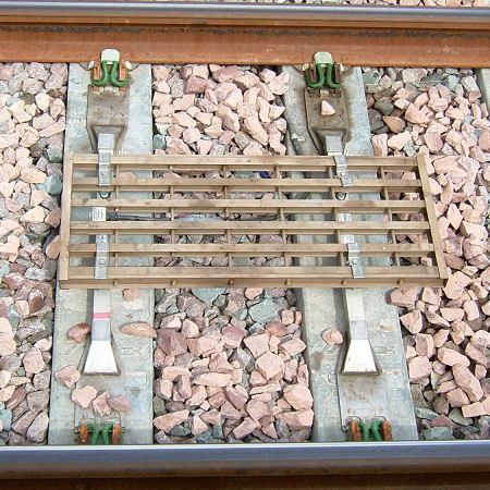
TPWS track equipment is configured to function either as a 'Train Stop System' (TSS) or an 'Overspeed System' (OSS). Every TPWS-fitted signal has a TSS placed near the signal, and most also have one or more OSS some distance (between 25 and 450 metres) on approach. The TSS and OSS each consist of a pair of transmitter loops mounted in the centre of the 'four-foot'. The first loop in any pair, in the direction of travel to which it applies, is termed the 'arming loop', and the second loop is the 'trigger loop'. The general arrangement is depicted in figure 1. Each loop is capable of transmitting one of the six available frequencies, referred to as 'f1' to 'f6'. The loops are only energised while the signal is displaying a 'danger' aspect. A loop consists of a wire running around the perimeter of a rectangular plastic grid, 1000 mm in length and 440 mm wide.

|
| Fig. 1: Standard TPWS Fitment. |
|---|

|
| Fig. 2: A TPWS transmitter loop. |
|---|
Ideally, the TSS is installed immediately alongside the applicable signal, but physical constraints might demand that it be positioned a short distance away. Special circumstances can require a signal to be provided with more than one TSS. A second TSS may be installed beyond the signal where a 'standing out' facility exists, or on the approach to a platform starting signal so that a train that starts some distance back and accelerates towards a red aspect can be stopped before it reaches the signal.
The decision as to whether or not an OSS should be provided depends on the effectiveness of the TSS. In the majority of cases, the TSS on its own would not be able to stop a train travelling at the maximum attainable speed within the safe overrun distance, thus requiring the addition of one or more OSS.
The 'set speed' of the OSS is the speed below which a train must pass to avoid a TPWS intervention. This is determined by the distance between the 'arming' and 'trigger' loops. For example, if the loops are placed 20 metres apart (measured from leading edge to leading edge), the set speed equals 46 mph for a passenger train, or 36.5 mph for a freight train. Greater separation results in a higher set speed. The further away the OSS trigger loop is from the signal, the higher the set speed has to be. On detecting an OSS arming loop, a 'trigger delay timer' on board the train starts running for a set duration (974 ms for passenger trains and 1218 ms for freight trains). The timer has different settings for freight trains and passenger trains to take account of their different braking characteristics. The timer should have completed its cycle before the trigger loop is detected, otherwise the train is deemed to running at excessive speed and a TPWS brake demand will occur.
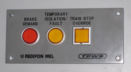
The two loops of a TSS abut so that their magnetic fields overlap. A brake demand occurs when a train, regardless of its speed, detects a TSS arming loop followed by the corresponding trigger loop frequency (while the arming loop frequency is still being detected). The trigger delay timer does not function at a TSS. The driver has a facility to override a TSS (because he or she may be instructed by the signalman to pass a signal at 'danger'), but an OSS cannot be overridden. A "Train Stop Override" button is located on a panel inside the driving cab, together with TPWS indications marked "Brake Demand" and "Temporary Isolation/Fault".

|
| Fig. 3: TPWS control panel (standard version). |
|---|
TPWS equipment only intervenes if the energised loops are encountered in the correct order (arming loop followed by trigger loop); therefore, the loops need not be suppressed for a move over them in the opposite direction. Two sets of frequencies exist to cater for the interleaving or nesting of loops on lines signalled in both directions. If just one frequency set was used, unwarranted interventions would result from an arming loop being wrongly paired with a nearby trigger loop that applied in the other direction. The frequencies are allocated as follows:
|
||||||||||||||||||
| Table 1: Allocation of Transmitter Loop Frequencies. |
|---|
Standard TPWS, with OSS loops placed no more than 450 metres from the signal as described earlier, is generally capable of stopping a train travelling at up to 75 mph inside the safe overrun distance. By installing an extra OSS at a greater distance from the signal, the effectiveness of TPWS for higher-speed applications can be increased. This type of fitment was originally called 'TPWS+', and the additional OSS was termed an OSS+. The OSS+ trigger loop was normally placed 750 metres from the signal, with the arming loop originally placed a further 28.3 metres on approach to give a set speed of 65 mph for passenger trains. The maximum distance for an OSS+ was later increased to 900 metres. The OSS+ can stop a train approaching at the maximum permissible speed, leaving the standard OSS only having to deal with trains approaching at a speed below the set speed of the OSS+. The terms TPWS+ and OSS+ are no longer used for new fitments requiring an OSS further than 450 metres from the signal.

|
| Fig. 4: TPWS+. |
|---|
Where TPWS+ would not give the desired protection, 'TPWS OS' (Outer Signal) may be fitted. With TPWS OS, no OSS+ is provided, but the next signal on approach is fitted with TPWS. When the junction protecting signal is at 'danger' and no forward route is set, the signal on approach will be held at red until the train has passed its OSS. This control is called 'conditional double red'. The outer signal's OSS was usually positioned at the maximum distance that was possible with standard TPWS (450 metres), to minimise delay to trains. The arming loop was 23 metres from the trigger loop, giving a set speed of 53 mph for passenger trains. A train travelling below that speed can be stopped inside the safe overrun distance by the TPWS fitted at the signal ahead.

|
| Fig. 5: A TPWS buffer stop mini-loop. |
|---|
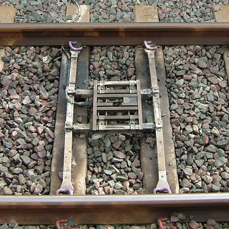
To help prevent buffer stop collisions on terminal platform lines, permanently energised OSS loops are installed on the approach to the buffer stops. Normally, the trigger loop is positioned 55 metres from the buffer stop, and to give a set speed of 12.5 mph, the arming loop is placed a further 5.5 metres on approach. Prior to 2006, the standard spacing for buffer stop OSS loops was just 4.5 metres, giving a lower set speed of 10 mph. When originally installed, the close spacing of these loops together with the behaviour of the train-borne equipment at very low speeds had led to trains frequently receiving TPWS interventions, despite their speed being below the set speed. These unwarranted interventions occurred when a train passed over the arming loop so slowly that its magnetic field was still being detected when the trigger delay timer completed its cycle. When this happens, the timer resets and immediately starts timing again, and if the trigger loop is detected during this second timing cycle, an intervention will occur. This can be prevented by increasing the space between the arming and trigger loops in which neither loop's field is detected by a train, but simply setting the loops further apart would raise the set speed. The solution that was implemented therefore entailed fitting smaller loops measuring 323 mm by 440 mm in place of the standard size loops, leaving the set speeds unaltered. These 'buffer stop mini-loops' were installed from 2002.
OSS loops are also fitted on the approach to some permanent speed restrictions (PSRs). The set speed for a PSR OSS is typically much higher than the maximum for a signal OSS; therefore, the arming and trigger loops can be spaced further apart than usual. Most PSR OSS loops are permanently energised. Self-powered OSS (SPOSS) loops, powered by batteries, were developed for use in connection with PSRs at places where no power supply is available. A treadle installed on the approach activates an economiser contact to conserve battery power. Some temporary speed restrictions (TSRs) may be fitted with TPWS if they are expected to remain in place for a long period of time.
Any TSS or OSS becomes totally ineffective if either the arming or trigger loop should fail to energise. TPWS equipment cannot therefore be considered as 'failsafe'. For this reason, a TPWS failure is protected by the previous signal being maintained at 'danger'. In addition, TPWS failures will usually be indicated in the signal box.
The simplified infrastructure of the No-Signalman Token Remote (NSTR) and Radio Electronic Token Block (RETB) systems has stop boards provided in place of worked stop signals. These stop boards may be fitted with TPWS, which is controlled by the issuing of tokens. The signalman receives no indication in the event of a TPWS failure, but TPWS status indicators are provided locally so that the train driver can confirm that the TPWS is working correctly. Normally a steady blue light is shown, indicating that the associated TPWS loops are energised. When a token is issued, the relevant blue light(s) will start to flash, meaning that the TPWS loops are de-energised. The loops remain de-energised for a set period of time, normally five minutes. The absence of a light indicates that there is a fault either with the TPWS equipment or with the indicator itself. The driver will advise the signalman of the fault. On NSTR lines, the indicators (one for each section) are located inside the cabinets housing the key token instruments. In RETB areas, the indicators (known as 'Lineside Status Indicators') are mounted below each TPWS-fitted stop board. Similar lineside indicators are also provided at NSTR crossing loops that have power-operated points.
|