|
|
|
Absolute Block is a method of working for use mainly on double or multiple track railways where each line normally carries traffic in one defined direction. The running lines are divided into block sections, each of which may only be occupied by one train at a time. Having originated before the invention of the track circuit, its safe operation depends on the strict observance of rules rather than relying on continuous train detection equipment.
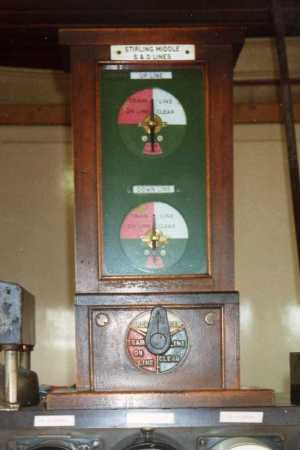
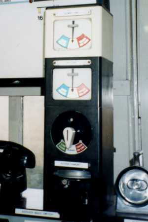
The signal boxes ('block posts') at opposite ends of a block section are equipped with block instruments, linked by electric line wires. The block instruments give both signalmen a continuous indication of the state of the block section. The indicators are either of the 'pegging' or 'non-pegging' type. A pegging indicator (or 'pegger'), situated at the exit end of the section to which it applies, has an associated commutator handle. Turning the commutator alters the pegging indicator of that instrument, as well the non-pegger at the entrance end of the section. The pegger and the non-pegger connected to the same adjacent block post are normally combined into one instrument, which shows the state of both block sections on the two adjacent running lines. The non-pegger is placed above the pegger in a combined instrument.
Until the 1870s, block instruments generally had commutators and indicators with just two positions, labelled "Line Clear" and "Train on Line" (or "Train Entered Section"). Later instruments have a third position, "Normal", alternatively called "Line Blocked" or "Line Closed".
The most common form of block indicator comprises a movable needle, which points to the appropriate indication. Some of the earliest block instruments, particularly two-position types, had small semaphore arms (working in the lower quadrant) as block indicators rather than needles. A block instrument that is built into a signalling control panel may indicate "Train on Line", "Normal" or "Line Clear" by the illumination of a red, white or green light, respectively.

|

|
|
| Fig. 1: Scottish Region block instrument. | Fig. 2: BR Standard block instrument. |
|---|
A bell circuit is also provided for each section, allowing signalmen to communicate with one another using a defined set of bell codes. The bell key ('tapper') at one end of the circuit operates the single-stroke bell at the other end. The bell and tapper can either be in a separate unit or incorporated into the block instrument. The regulations require that most bell codes be acknowledged by repetition. Certain bell codes must be preceded by the "call attention" signal, a single beat on the bell.
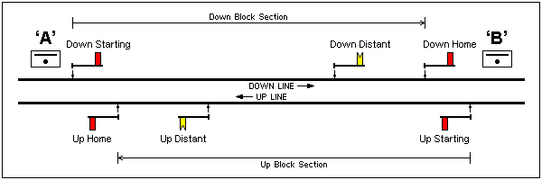
Generally, stop signals on approach to the controlling signal box are termed 'home signals', and those beyond it are 'starting signals'. The last starting signal, which admits trains into the block section, may also be referred to as the 'section signal'. The portion of line from the first home signal to the last starting signal, which is under the direct control of the signalman, is called 'station limits'. If there is only one stop signal on the line, however, 'station limits' do not apply, and the signal functions both as a home signal and a section signal. Signals can be in semaphore or colour light form.
Figure 3 represents a typical double track section between two signal boxes labelled 'A' and 'B'. A block section is under the control of the signalman at the exit end, hence signal box 'A' controls the Up line block section from 'B' and box 'B' controls the Down line section from 'A'. In the absence of any trains, the blocks will be at "Normal" and all signals will be kept in the 'on' position.

|
| Fig. 3: Double Track Section with Absolute Block. |
|---|
If the signalman at 'A' wishes to send a train into the Down line block section to 'B', he can only do so with the cooperation of the signalman there. Observing that his non-pegging block indicator is at "Normal", signalman 'A' knows that the section is clear but permission has not been granted for a train to approach signal box 'B'. Signalman 'A' asks signalman 'B' by bell code if the line is clear for the train. If the block section and the block overlap (see below) are clear, signalman 'B' acknowledges the bell code and turns his commutator to "Line Clear". The section signal at 'A' may now be cleared for the train. Signalman 'A' advises signalman 'B' when the train enters the section, with the bell code "train entering section". Signalman 'B' acknowledges the bell code and turns the commutator to "Train on Line".
Having travelled through the block section, the train arrives at 'B'. The signalman there must observe the tail lamp on the rear of the train as it passes, as proof that no part of the train has been left behind in the block section. Having done so, and provided the train has passed beyond the clearing point (see below), he sends the "train out of section" bell code to signalman 'A' and turns his commutator back to "Normal".
If the block section is track circuited throughout, signalmen may be exempted from observing tail lamps. Alternatively, a relatively recent development is the erection of tail lamp cameras at certain locations where the signalman is not able to observe the rear of trains as they leave the section. The signalman instead looks for the tail lamp on a monitor inside the signal box.
The block regulations usually require that, when a train is accepted, the line must be clear for a defined distance beyond the first home signal, up to what is called the 'clearing point'. This provides a safety margin in the event of a train passing the home signal at 'danger'. The portion of line from the home signal to the clearing point is called the 'block overlap', and traditionally it is a quarter of a mile (440 yards / 402 metres) in length but can be shorter under certain circumstances, for example if the distant signal is a colour light.
Where authorised, or during emergency, trains may be accepted into the block section while the block overlap is obstructed. The driver was advised by one of various means that the train will be going forward under the 'Warning Arrangement' (also known as 'Regulation 5'), usually by the signalman cautioning the train at the home signal then exhibiting a green flag as it approached the signal box. Once the driver had acknowledged the handsignal by giving a short whistle, the section signal could then be cleared; otherwise, the train would first be brought to a stand at it. At locations where trains were regularly admitted into the section under the Warning Arrangement, a subsidiary warning signal was provided at the section signal.
The addition of controls to the basic Absolute Block system helps to enforce its correct operation and guards against error on the part of the signalman. Figure 4 shows the application of block controls at a typical block post.

|
| Fig. 4: Example Block Post provided with Block Controls. |
|---|
Section signals are usually provided with Line Clear Release (LCR) to prevent them from being cleared unless the block is at "Line Clear". The lever that operates the signal is fitted with an electric lock. The release should only be effective for one train and there were three principal methods of achieving this, one known as 'one pull', another as 'one train', and one that allowed the section signal to be cleared repeatedly as long as the track circuit on approach to it was clear. Line Clear Release was first introduced at Southampton on the London & South Western Railway in 1870.
An idea pioneered by the Lancashire & Yorkshire Railway was the provision of a short 'berth' track circuit on the immediate approach to the outermost home signal, which will place or maintain the block indicators at "Train on Line" irrespective of the commutator's position. This prevents the signalman from inadvertently turning the block to "Line Clear" thereby allowing a second train to be admitted into the section, if he has forgotten about the first train waiting at the home signal. It may also operate an audible annunciator when the home signal is at 'danger'. To restore the block, the track circuit must have cleared and the commutator must have been turned to "Train on Line".
Normal Control (NC) proves that the distant signal is at 'caution' before "Line Clear" can be given. This was first used in 1911 on the Great Western Railway and is sometimes called 'interlinking'. It proves that the distant signal has not stuck in the 'off' position. Later, it became practice to interlink the outermost home signal by electrically proving that its controlling lever is in the 'normal' position before "Line Clear" can be given. This is termed Home Normal Control (HNC) and forces the signalman to replace the signal to 'danger' behind a train before accepting another train into the block.

|
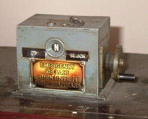
| Fig. 5: Welwyn Control emergency release. |
|---|
Sequential locking prevents a stop signal from being cleared when the next stop signal ahead (and worked from the same signal box) is 'off'. It therefore compels the signalman to replace all the stop signals to 'danger' behind every train rather than leaving them cleared. Sequential locking can be accomplished either mechanically or electrically.
Welwyn Control prevents the block from being turned to "Line Clear" while a train is in the section. A train is proved to have passed right through the section by it occupying then clearing the berth track circuit at the home signal. Having done so, "Line Clear" can be given again to admit the next train into the section. An emergency time release is provided to override the Welwyn Control in the event that "Line Clear" has been given for a train which is subsequently cancelled and does not require to enter the section. When operating this device, an enforced time delay passes before the release becomes effective, giving the signalman a period of time in which to consider his or her actions. The introduction of Welwyn Control was a recommendation of the report into a fatal rear-end collision on 15 June 1935 at Welwyn Garden City on the LNER, when the signalman had overlooked a train already in the section.
All the controls mentioned above are in widespread use. Many of them are equally relevant to the Electric Token Block system for single line railways.
The provision of intermediate block (IB) signals divides a block section so that capacity is improved without the need for another signal box. Although different arrangements have existed, intermediate block signals are most commonly worked from the signal box on approach, i.e. the Down IB signals seen in figure 6 are controlled from signal box 'C'. The intermediate block home signal is preceded by its own distant signal, which is usually worked from the same lever. The ordinary distant signal for the signal box can be cleared while the IB signals are 'on'.
The portion of line between the section signal and the intermediate block home signal is referred to as the 'intermediate block section' and is continuously track circuited. The starting signal controls entry into the intermediate block section and is electrically locked at 'danger' unless the line is clear to the IB home signal and the overlap beyond it is clear. The IB home signal controls entry into the block section and is provided with Line Clear Release. Intermediate block signals are usually too far from the signal box to be mechanically operated and so generally are colour light signals or, less frequently, motor-operated semaphores. There can be consecutive IB sections between the same two signal boxes, although this is unusual.

|
| Fig. 6: Intermediate Block Sections. |
|---|
Many signal boxes have the facility to 'switch out' when not required, whilst allowing trains to continue running (albeit with a reduction in line capacity). A 'block switch' is provided, which disconnects the block instruments at that signal box and connects the block circuits on either side, effectively merging the two adjacent block sections into one (along with any intervening station limits or intermediate block sections). The signals controlled from the signal box remain 'off' for through running while it is switched out. Not every signal box is able to switch out. Generally, a signal box cannot switch out if it controls a level crossing or if the method of working is different on either side (e.g. Absolute Block in one direction and Track Circuit Block in the other).
|