Signal Aspect Sequences
(Page 1 of 1)
A main signal's aspect is determined not just by whether or not the line ahead is clear but also by the aspect displayed at the next signal ahead. A stop signal displaying a 'danger' aspect must be preceded by at least one cautionary aspect (this does not apply if the signal cannot be approached under the authority of a main aspect). A driver approaching a signal at 'danger' will be presented with a sequence of one or more 'caution' aspects at the previous signals, to advise him or her that braking should commence.
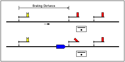
With semaphore signalling, the simplest aspect sequence arises when every stop signal is preceded by a distant signal, with full braking distance between the two. In this situation, the distant signal simply acts as a repeater of the stop signal ahead in that it will only show 'clear' if the associated stop signal is also showing 'clear'. If the stop signal is 'on', the distant signal must also be 'on'.
Most signal boxes control more than one stop signal on each running line. Consecutive stop signals controlled from the same signal box need not be spaced at braking distance apart. Usually only one distant signal is provided (there are some exceptions), it being located at braking distance from the first stop signal. The distant signal can only be cleared when all the stop signals have been cleared. When it is not possible to clear all the stop signals, the distant signal is maintained at 'caution'. The working of consecutive semaphore stop signals was prescribed in Rule 39 (a) of the old Rule Book as follows:
"When a stop signal is at Danger the stop signal next in rear of it and worked from the same signal box must not be lowered for an approaching train until the train is close to such signal and has been brought quite or nearly to a stand."
This rule exists because a semaphore stop signal in the 'off' position only indicates to the driver that the line is clear to the next stop signal; it does not inform whether or not the next signal is 'off'. Applying Rule 39 (a) advises the driver to expect the next signal at 'danger'. It must be carried out at each stop signal in turn, until such time as all signals ahead of the train (and controlled from the same signal box) are able to be cleared.
Advances in signalling technology in the early 20th century made it feasible for a signal box to control many miles of railway, with signals positioned at regular intervals. In some circumstances the signals could be made to work automatically. It is not practicable to apply Rule 39 (a) over long distances with many signals as serious delay to trains would result, nor is it practicable for one distant signal to apply to a large number of stop signals, as the opportunity to clear it would seldom arise. The alternative is to equip every stop signal so that it acts as a distant for the next signal. Under this scenario, full braking distance must exist between each signal and the next.
Three-position semaphore signals were able to show three indications ('danger', 'caution' and 'clear') with just one arm, thus avoiding the need for separate stop and distant arms on the same post. Three-position semaphores operated in the upper quadrant so that drivers could distinguish them from the ordinary two-position semaphores, which at that time were invariably of the lower quadrant type. In contrast to a two-position semaphore arm, a three-position arm inclined at 45° conveys an unambiguous meaning of 'caution'.
Three-aspect colour light signals were first introduced in 1923. Their aspects (red, yellow and green) were directly equivalent to the indications given by three-position semaphores.
The addition of a fourth aspect, double yellow, to the colour light sequence allowed the signals to be spaced at less than braking distance, thereby improving line capacity.
The experimental speed signalling brought into use at Mirfield in July 1932 included a fifth aspect, yellow over green. Preceding a double yellow aspect, the yellow over green aspect meant "attention - pass second signal at restricted speed". This extra cautionary aspect allowed the signals to be spaced even more closely together. Although the yellow over green aspect was to be discontinued, a sequence involving consecutive double yellow aspects could be used where signals needed to be closely spaced.
Figure 7 also illustrates the use of red marker lights, which were a feature of the Mirfield scheme and three other contemporary colour light signalling installations on the LMS. The primary purpose of the marker light was to identify the signals as being within 'multiple-aspect colour light signal' territory (where every signal acts as a distant signal for the one ahead). After a few years of operation, the marker lights were altered so as to be illuminated only when the corresponding signal was at 'danger'.
In May 1988, most of the existing four-aspect signals on the Fast lines between Peterborough and Stoke Tunnel on the East Coast Main Line were modified to cater for special test runs of the new Class 91 electric trains at speeds of up to 140 mph. The signal spacing did not provide sufficient braking distance between the double yellow and red aspects for trains approaching at speeds in excess of 125 mph. The solution was to introduce a flashing green aspect as an indication that the next signal was showing either flashing green or steady green. For the test trains, a flashing green aspect gave authority to exceed 125 mph, and a steady green aspect meant "reduce speed to 125 mph". For all other trains, a flashing green aspect means the same as a steady green.


