|
|
|
The mechanical trainstop system is a rudimentary train protection system, typically used on DC electrified railways in urban areas where all trains have similar braking characteristics. Some of the lines where trainstops were installed are listed below.
|
|||||||||||||||||||||||||||
| Table 1: Lines fitted with the Mechanical Trainstop System. |
|---|
The principal track-based and train-borne components of the system are trainstops and tripcocks, respectively.
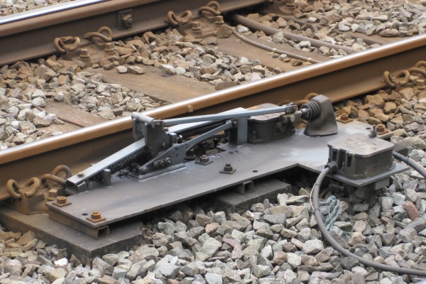
Trainstops are installed beside the track at stop signals and certain other places, and are positioned outside the right-hand running rail in the applicable direction of travel. Each trainstop has a movable arm that is electrically operated by the signalling system. The arm on most trainstops normally stands in the raised (effective) position, and it will automatically return to that position if power to it is lost. The arm is moved to the lowered (ineffective) position for the authorised passage of a train (in either direction).
A tripcock is situated near the front of each train, on the right-hand side in the forward direction of travel. If a train passes a trainstop while the arm is in the raised position, the tripcock physically engages with the arm and is pushed back to initiate a brake application. A visual indication is presented to the driver when this occurs. The brake application and visual indication are maintained until the train has stopped or nearly stopped and the driver resets the system.
Most trainstops are located at stop signals. The trainstop's arm is raised when the adjacent signal is at 'danger'. A signal that is being cleared continues to display a 'danger' aspect until the trainstop's arm is proved to be in the lowered position. A multi-unit colour signal may display 'danger' and 'proceed' aspects simultaneously while the arm is lowering, which takes about two seconds. The purpose of showing both aspects together is to alert the driver to a trainstop that has failed to fully lower. Since a single-aperture colour light signal is unable to show two aspects simultaneously, a 'proceed' aspect is not displayed until the arm is fully lowered.

|
| Fig. 1: Trainstop (arm in raised position). |
|---|
The tripcock on a train that passes a signal at 'danger' will engage with the raised trainstop arm and initiate a brake application. The overlap beyond the signal is designed to have sufficient length for a train travelling at the permissible speed to stop within it when a brake application is initiated at the trainstop. Where this is unachievable with a trainstop at the signal alone, additional trainstops can be provided on the approach to it for speed control purposes (see below) to ensure that a train will stop within the overlap.
Trainstops can be installed for speed control purposes to check that a train is not exceeding a particular set speed when it passes. These trainstops may be provided on approach to speed restrictions, buffer stops and stop signals with short overlaps. The arm on these trainstops moves to the lowered position only when an approaching train has occupied the relevant track circuit for a period of time calculated to determine that its speed is sufficiently low. If the train approaches at a speed below or equal to the set speed, the trainstop's arm lowers before the train arrives, but if it approaches at a speed higher than the set speed, the arm remains raised and initiates a brake application. When provided on approach to a buffer stop, this feature is known as 'Moorgate Control' in reference to the accident that occurred at the Northern City Line's Moorgate terminus on 28 February 1975.
A trainstop with an arm permanently fixed in the raised position may be provided at the end of a terminal platform line to apply the brakes on any train that overruns the stopping point.
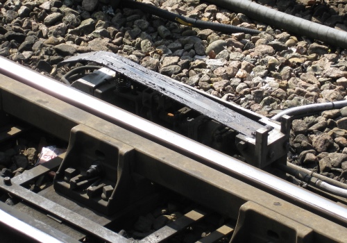
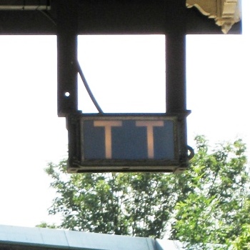
The protection afforded by the trainstop system is dependent on trains' tripcocks being set in the correct position to engage with a raised trainstop arm. Tripcock testers and associated indicators are provided on the approaches to areas with trainstop protection to indicate to drivers that the tripcock on their train is correctly positioned. When a train occupies a track circuit on approach, the indicator illuminates to display the letters "TT". The indication remains lit until the train's tripcock depresses a sprung ramp on the tripcock tester, which is positioned close to the indicator. If the indicator continues to show "TT", the driver must assume that the train's tripcock is not in the correct position. A tripcock that is out of the correct horizontal alignment will strike one of the gauge posts at the start of the ramp and initiate a brake application. The tripcock tester operates independently of any trainstop equipment.

|

|
|
| Fig. 2: Tripcock tester. | Fig. 3: Tripcock test indicator. |
|---|
A tripcock striking a raised trainstop arm at speed could potentially damage the trainstop. When multiple units are coupled together to form a longer train, the tripcock on the second unit is held in a raised position to prevent it from making contact with any raised trainstop arms. To detect a lowered tripcock on the second unit, 'sacrificial' trainstops are provided on approach to the last signal before the start of an area with trainstop protection. The arms on these trainstops are normally lowered. The arm rises between the fronts of the first and second units passing it, being activated by the first wheel of the train occupying the overlap track circuit, and returns to the lowered position when the train clears the relevant track circuits. The position of this trainstop is determined by the boundary between the berth and overlap track circuits, and not by the signal.
Sacrificial trainstops are not interlocked with the signal, but the signal cannot display a 'proceed' aspect unless the trainstop's arm is proved to be in the lowered position.
|