|
|
|
The gradient of the railway trackbed is seldom constant over any considerable length, and it may change several times within the space of a mile. Gradients that are particularly steep can affect the working of some trains to the extent that special operating procedures may be necessary.
The North Midland Railway was one of the first companies to indicate gradients at the lineside, which was done by conspicuous markings on every milepost, showing the steepness of the gradient and the direction of the slope at that location. The rate of inclination of the gradient was expressed as a fraction as well as in feet per mile, and a thick line indicated the direction of ascent or descent.
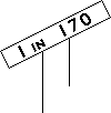
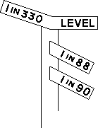
The general introduction of gradient posts was recommended by the Board of Trade following an accident at Chesterford (Eastern Counties Railway) on 4 August 1845. A post was to be placed at each location where the gradient of the trackbed changed. Most gradient posts comprise a pair of arms facing the track, one on either side of a post. The arms are inclined up or down to indicate the direction of the slope, and each one has the rate of inclination of the relevant gradient marked on it [24.1 & 24.2]. The rate of inclination is expressed as a ratio, e.g. "1 in 200" (or "1:200"). For example, "1 in 500" means that the track rises (or drops) one unit for every 500 units travelled horizontally. Note that a smaller number in the second part of the ratio indicates a steeper gradient. Some patterns of gradient post omit the first part of the ratio, the value of 1 being implicit [24.3].
If the trackbed in one direction is level, the corresponding arm of the gradient post is horizontal and bears the word "level" [24.4] or just the letter "L" [24.5]. A level gradient can alternatively be expressed as "1 in ∞", since an infinite number of units would need to be travelled for the track to rise or fall by one unit [24.6].
|
The Highland Railway installed separate gradient posts on either side of the line, each showing the gradient in one direction only [24.7]. |
|
As an alternative to a pair of arms, the direction of the slope can be indicated by inclined bars on a rectangular board. The bars on either side of the board may be separate [24.8], or they may be joined [24.9]. The gradient values are generally displayed above each bar. Some gradient posts on the Scotland Route have joined bars that can extend to the top of the board, requiring some values to be displayed below the bar [24.10]. An unusual method of presentation superimposes the gradient values on wide bars [24.11].
Special forms of gradient posts could be provided at junctions where the gradient of the diverging branch line differs from that of the main line. The gradient at the start of the branch line may be indicated by a gradient post with a single arm projecting in the direction of the branch [24.12]. A gradient post comprising a single arm centred on the post provides confirmation of the main line gradient through the junction [24.13]. Exceptionally, where a junction coincided with a change of gradient on the main line, a gradient post could be provided with extra arms showing the branch line gradients [24.14].
 |
 |
 |
|
[24.12] Gradient Post for a Junction (showing the branch line gradient).
Area: Various Usage: Medium Status: Current |
[24.13] Gradient Post for a Junction (showing the main line gradient).
Area: Various Usage: Medium Status: Obsolescent |
[24.14] Gradient Post for a Junction (showing main and branch line gradients).
Area: Various Usage: Low Status: Historical |
|---|
|
Where necessary, a gradient post may be fitted with an additional plate indicating to which line or lines it refers [24.15]. |
|
Special precautions were often necessary when working unfitted freight trains down steep inclines, to avoid the train getting out of control. The Great Western Railway was the first company to introduce a practice that required these trains to come to an absolute stop at the top of the incline. The guard would then manually apply a sufficient number of wagon brakes to keep the train under control on its descent. After descending the incline, the train would stop again; this time, to allow the wagon brakes to be released. A worded notice board was provided at the top of the inclines where these procedures had to be carried out [24.16 & 24.17]. Other companies that adopted the same practice installed boards with alternative wording, whereas the LNER provided signs with just a letter "B" for "brakes" [24.18]. Later signs had the letters "AWB" for "apply wagon brakes" [24.19 - 24.21]. At some locations, a standard stop board (see [26.15]) was used, with the wording "Stop - Freight train wagon brakes to be applied".
 |
 |
 |
|
[24.16] Incline Stop Board (e.g. Up direction trains).
Area: GWR Usage: Medium Status: Historical |
[24.17] Incline Stop Board (e.g. Down direction trains, with 35 wagons or less).
Area: GWR Usage: Low Status: Historical |
[24.18] "B" Sign.
Area: LNER Usage: Medium Status: Historical |
|---|---|---|
 |
 |
 |
|
[24.19] "AWB" Sign.
Area: Elgin - Keith Usage: Low Status: Historical |
[24.20] "AWB" Sign.
Area: London Midland Region Usage: Low Status: Obsolescent |
[24.21] "AWB" Sign.
Area: All Areas Usage: Medium Status: Obsolescent |
|
Some goods trains bound for British Railways' Southern Region via the London Underground's "City Widened Lines" required to be banked up the incline between Holborn Low Level and Holborn Viaduct by an assisting locomotive. Alterations were made in the Farringdon area in July 1958 to enable the working of longer goods trains, including the provision of apparatus that allowed the driver of a train requiring assistance to exchange visual signals with the driver of the banking engine. A number of banking signs were provided, which displayed a letter "B" when illuminated [24.22]. Some of these signs were double-sided. When the assisting locomotive was ready to assist at the rear of the train, its driver either reached out from the cab window and pinched together two wires fixed to the tunnel wall or operated a plunger, causing the relevant banking signs to illuminate after a delay of one minute. This indicated to the driver of the goods train that the assisting engine was ready. When the goods train had a clear signal and was ready to proceed, its driver pinched together a different pair of wires, which caused another set of banking signs to illuminate to inform the driver of the assisting engine that the train was ready to proceed up the gradient. Banking indicators were also provided on certain platforms at Birmingham New Street station to indicate to bank engine drivers that all signals were 'off' as far as Church Road Junction. These indicators replaced a special banking signal. |
|
The Severn Tunnel is over four miles (6.5 km) in length, with long steep gradients. A short section of level trackbed near the middle of the tunnel is approached from the Welsh end on a 1 in 90 falling gradient and from the English end at 1 in 100 falling. Marker lights are fixed to the tunnel walls in both directions, indicating the approach to the change of gradient. When originally installed (by 1966), these comprised a single white light [24.23] at a quarter of a mile (0.4 km) followed by two white lights [24.24] at 40 yards (36 metres) from the point where the falling gradient changes to level. To maintain a tight coupling, drivers of freight trains descending the gradient were required to release the brakes gradually before passing the single light and apply power before reaching the double lights.
Additional lights for reverse direction movements were installed in 1989 when bi-directional signalling was commissioned through the tunnel. In May 1992, the colour of the lights was altered from white to blue [24.25 & 24.26].
 |
 |
|
[24.23] Gradient Marker Light.
Area: Severn Tunnel Usage: Low Status: Historical |
[24.24] Gradient Marker Lights.
Area: Severn Tunnel Usage: Low Status: Historical |
|---|---|
 |
 |
|
[24.25] Gradient Marker Light.
Area: Severn Tunnel Usage: Low Status: Current |
[24.26] Gradient Marker Lights.
Area: Severn Tunnel Usage: Low Status: Current |
|
Experience with the disc brakes fitted to Class 158 diesel multiple units in severe weather conditions led to the introduction of special instructions requiring drivers to regularly test the brakes while driving. In addition, special signs depicting a snowflake symbol on a white triangle with a red border [24.27] were provided on the approaches to Druimuachder and Slochd Summits (between Perth and Inverness) in January 1995. During freezing conditions or when snow is falling (or when fallen snow may be disturbed by passing trains), drivers of Class 158 trains are required to make a full service brake application and stop at these signs before proceeding. Similar signs were provided at Beattock Summit on the West Coast Main Line in January 1996. |
|
|