|
|
|
|
|
|
|
|
|
|
As an alternative to the provision of separate signals for each route, a route indicator may be used in conjunction with a single signal. This is especially advantageous where there is a great number of routes, such as on the approach to a large station. The London, Brighton & South Coast Railway was the first company to use route indicators, the first of these being provided at London Bridge in 1878. When a signal equipped with a route indicator was at 'danger', no route indication was visible, but when it was cleared, a white enamelled disc dropped into view. The black character (letter or number) exhibited on the disc indicated which route was set from that signal [6.14]. The discs were illuminated at night by oil lamps that reflected light upon them, but this proved to be unsatisfactory. |
|
Directional shunting signals of the three-position banner type were used in a few places, e.g. Glasgow St. Enoch (Glasgow & South Western Railway) in July 1898. The arms of these signals could rotate either to the left [6.15] or to the right [6.16] when cleared, to indicate the direction of route.
 |
 |
|
[6.15] Directional Banner Shunting Signal (left-hand route set).
Area: Various Usage: Medium Status: Historical |
[6.16] Directional Banner Shunting Signal (right-hand route set).
Area: Various Usage: Medium Status: Historical |
|---|
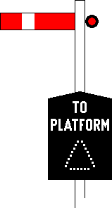
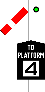
The first successful type of route indicator was designed by J P Annett, Chief Signal Superintendent of the London & South Western Railway, and patented by him in 1902. The indications were illuminated from behind, which was a great improvement on the original design of route indicator (see [6.14]). A shutter covered the indicator's aperture while no character was on display. Through an arrangement of holes in the shutter, a triangle formed of white lights was visible while the signal was at 'danger' [6.17]. The shutter rose when the signal cleared, revealing a route indication inside the aperture [6.18].
 |
 |
|
[6.17] Route Indicator (signal 'on').
Area: Various Usage: Medium Status: Historical |
[6.18] Route Indicator (signal 'off'; e.g. "4" displayed).
Area: Various Usage: Medium Status: Historical |
|---|
The actual characters displayed by route indicators differ from place to place and drivers must learn their applications in each individual case. Accordingly, it is not possible to list every indication along with its meaning as these vary between signals in different locations. For example, the letter "B" can mean "Branch line" at one signal and "Bay platform" at a different signal. Any one route indication should, however, have the same application on all signals in the same locality. Certain indications are commonly assigned to specific applications. A number is frequently displayed to indicate a platform road, and the letter "X" often refers to a wrong-direction movement, e.g. towards a 'limit of shunt' indicator (see Section 5). Where a destination could be reached by either of two alternative routes through the track layout, the LNER typically supplemented the route indication with a direction arrow pointing left or right, e.g. "←UM" and "UM→" for alternative routes to the Up Main line.
|
The stencil type route indicator was first used at Birmingham Snow Hill (GWR) in 1910. This type of route indicator has no moving parts and comprises a separate compartment for each indication, each consisting of a stencil character illuminated from behind by an electric lamp [6.20]. |
|
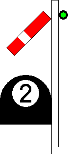
In 1910, Sykes introduced a form of route indicator in which a character was exhibited inside a banner type shunting signal when cleared [6.21]. In the same year, they designed an electrical route indicator that was similar but was contained in a separate housing [6.22]. At first, this indicator was of a small size suitable for use only with shunting signals, but a larger version was later developed for use on main signals.
 |
 |
|
[6.21] Banner Type Shunting Signal ('off') with Route Indication (e.g. "4" displayed).
Area: Unknown Usage: Low Status: Historical |
[6.22] Route Indicator (e.g. "2" displayed).
Area: Various Usage: High Status: Historical |
|---|
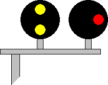
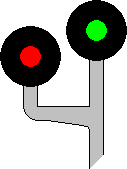
The earliest colour light junction signals for high-speed divergences perpetuated the established practice applicable to semaphore signals, as recommended by the report of the IRSE's Three-Position Signalling Committee, published in 1924 (see also Section 2). A colour light junction signal was therefore provided with a separate signal head for each route [6.23]. Where appropriate (excluding the Southern Railway), the heads were stepped in height according to the relative speed of each route [6.24], as with semaphore signalling practice. For low-speed divergences and complex areas such as large stations, a colour light junction signal was generally provided with an electrical form of route indicator. Exceptionally, both methods of indicating the route could be implemented in combination on a signal with three or more routes, in which case one of a pair of signal heads was provided with an associated route indicator.
 |
 |
|
[6.23] Colour Light Junction Signal (e.g. left-hand route set; signal at 'preliminary caution').
Area: All Areas Usage: High Status: Historical |
[6.24] Colour Light Junction Signal (e.g. right-hand (higher speed) route set; signal at 'clear').
Area: All Areas except Southern Railway Usage: High Status: Historical |
|---|
Splitting distant signals (see [6.6]) were initially considered to be incompatible with three or four-aspect signalling. The Three-Position Signalling Committee's report had recommended that a colour light distant signal on the approach to a junction signal should show a double yellow aspect (see [2.108]) when the lower-speed diverging route ahead was set. The LNER adopted this practice, as did the LMS after an accident occurred at Great Bridgeford on 17 June 1932, when a train became derailed while crossing from the Up Slow line to the Up Fast line at excessive speed. The practice was discontinued, however, following a subsequent derailment at Bourne End, on 30 September 1945. The train involved in that accident became derailed while crossing from the Up Fast line to the Up Slow line after passing a double yellow aspect at the distant signal on approach to the semaphore junction signal.
Another recommendation within the Three-Position Signalling Committee's report had suggested that, where neither route required a reduction in speed, the junction distant signal should display a 'clear' aspect together with an illuminated indicator showing either "L" or "R" for the left-hand route or right-hand route, respectively. For any lower-speed routes from the same junction signal, the indicator was to show the permitted speed, in miles per hour, together with a double yellow aspect. This idea was not put into practice.
The mid-1920s saw the introduction of two new types of route indicators, both of which were suitable for use with main signals and were able to display different indications in the same position without requiring any moving parts. One of these formed the character to be displayed by illuminating the appropriate lamps within a matrix [6.25]. This is known as the 'theatre' or 'multi-lamp' type route indicator, the former name deriving from its similarity to a form of act number indicator exhibited to the audience in music hall theatres. Westinghouse produced the optical projector type route indicator [6.26]. These did not give a good indication in sunlight, and latterly their provision was restricted to covered stations, etc.
 |
 |
[6.25] 'Theatre' or 'Multi-Lamp' Type Route Indicator (e.g. "A" displayed).

Area: All Areas Usage: High Status: Obsolescent |
[6.26] Optical Projector Type Route Indicator (e.g. "5" displayed).
Area: Various Usage: High Status: Historical |
|---|
Alphanumeric route indicators are not suitable for high-speed running. An alphanumeric route indicator may be provided on a high-speed line if no indication is displayed for the high-speed route, an indication being displayed only for a low-speed divergence.
|
|
|