Section 6: Junction Signals and Route Indicators
(Page 4 of 5)
A three-aspect colour light signal, number UC4B, had been brought into use in February 1935 at Hackney Downs (LNER), accompanied by directing distant heads that could display yellow or green lights, stepped in height (see [6.31]). Since it would be undesirable for a directing distant head of this type to show a green light while the main signal head displayed a more restrictive double yellow aspect, an alternative method of displaying advance routeing information was implemented at signal UC4B when it was converted to four-aspect type in November 1935. The directing distant indications were removed and replaced with special route indicator lamps somewhat reminiscent of the suggestion in the IRSE Three-Position Signalling Committee's report of 1924 that certain colour light junction distant signals should be fitted with indicators that display either "L" or "R", for the left-hand or right-hand route. The indicator lamps at signal UC4B exhibited the indications "F" or "S", referring to the Up Fast or the Up Suburban line, respectively, and they were appropriately positioned on either side of the signal post and stepped in height. When that signal and the junction signal beyond were both cleared, one of the indicator lamps exhibited the appropriate indication for the route set at the junction [6.43 & 6.44]. This form of advance route indicator was not replicated elsewhere, and those at Hackney Downs remained in use until May 2001.
 |
 |
[6.43] Route Indicator Lamp indicating junction signal ahead cleared for route to Up Fast line (e.g. 'clear' aspect).
Area: Hackney Downs, LNER
Usage: Low
Status: Historical
|
[6.44] Route Indicator Lamp indicating junction signal ahead cleared for route to Up Suburban line (e.g. 'preliminary caution' aspect).
Area: Hackney Downs, LNER
Usage: Low
Status: Historical
|
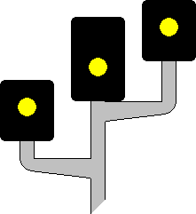
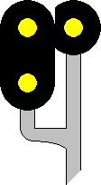
In what became the standard form of colour light splitting distant signal, multiple signal heads are positioned side by side and stepped in height according to the relative speeds of the routes. If required to also act as a stop signal, one of the heads in the splitting distant signal is capable of displaying a red 'danger' aspect. When the junction signal was at 'danger', the splitting distant signal (providing it was not itself at 'danger') displayed a single yellow aspect in each of its heads [6.45]. When the junction signal was cleared, the appropriate head stepped up to a higher aspect (double yellow or green) [6.46]. It was exceptional for this form of splitting distant signal to have as many as three heads.
 |
 |
[6.45] Colour Light Splitting Distant Signal showing single yellow in each head (e.g. three heads).
Area: All Areas
Usage: Medium
Status: Obsolescent
|
[6.46] Colour Light Splitting Distant Signal (e.g. junction signal ahead cleared for a (lower speed) left-hand route; signal at 'preliminary caution').

Area: All Areas
Usage: Medium
Status: Current
|
On the Cheshire Lines Committee, a variant form of directing miniature colour light shunting signal (see [6.37 & 6.38]) was used where associated with a main signal (see also [4.79]). When cleared for the left-hand route, a green light was displayed above a letter "S" [6.47], and when cleared for the right-hand route, a green light was displayed below the letter "S" [6.48]. No aspect was displayed when the shunting signal was 'on'.
 |
 |
[6.47] Directing Miniature Colour Light Shunting Signal associated with a main signal, 'off' for left-hand route.
Area: CLC
Usage: Low
Status: Historical
|
[6.48] Directing Miniature Colour Light Shunting Signal associated with a main signal, 'off' for right-hand route.
Area: CLC
Usage: Low
Status: Historical
|
|
Following the introduction of position light shunting signals (see [4.73 & 4.74]), it became customary for two signals of that type to be positioned one above the other where it was required to indicate which one of two routes was set [6.49]. In accordance with traditional practice, the top signal referred to the left-hand route. If more than two routes needed to be indicated, a route indicator was provided in conjunction with a single signal head. The practice of providing two position light signals together for route indicating purposes was discontinued from c.1960.
|
 |
[6.49] Two-Tier Position Light Shunting Signal (e.g. white light type; 'off' for right-hand route).

Area: All Areas
Usage: High
Status: Obsolescent
|
|
The LNER's trial of junction indicators at Thirsk (see [6.41 & 6.42]) led the Southern Railway to adopt a modified form of junction indicator as standard. The vertical indicator for the straight route (see [6.41]) was deemed unnecessary and was dispensed with. The newer style of junction indicator comprised a row of three white lights in each arm [6.50], a throwback to A E Tattersall's earlier experiments with position light type main signals on the Metropolitan Railway (see [2.88 - 2.90]). The Southern Railway began installing three-lamp position light junction indicators in May 1936, with its resignalling between London Waterloo and Hampton Court Junction. The LNER installed one of the same type at Hall Farm Junction in January 1938 as part of its Chingford Branch resignalling scheme.
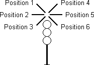
On any individual colour light signal, a maximum of three junction indicator arms can be placed to the left-hand side and, likewise, a maximum of three to the right-hand side. The six permitted junction indicator positions are referred to by number; positions 1, 2 and 3 are for routes to the left of the straight route and positions 4, 5 and 6 are for routes to the right [6.51]. If only one diverging route exists to the left or right of the straight route, it will be indicated by a position 1 or position 4 junction indicator arm, as appropriate; these positions are inclined at an angle of 45° from the vertical. Additional diverging routes can be catered for by adding further indicator arms (up to a maximum of three, as already stated) at progressively lower heights and increasing angles of inclination. Each additional arm is inclined at an angle of 45° greater than the one immediately above it. Where a signal is provided with more than one junction indicator arm on the same side (e.g. positions 1 and 2), the indicator at the lowest height applies to the route that diverges furthest from the straight route. A junction indicator arm is commonly referred to as a 'feather'.
 |
 |
[6.50] Three-Lamp Junction Indicator (e.g. Position 1).

Area: Predominantly Southern Railway
Usage: High
Status: Historical
|
[6.51] Junction Indicator Positions. *
Area: All Areas
Usage: High
Status: Current
|
| * Note: |
The illustration above right serves only to show the positions of the junction indicator arms, which are described elsewhere in this section. |
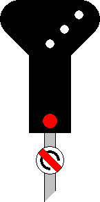
A main signal with a junction indicator may also have a subsidiary signal (see Section 3) that can apply along the route(s) for which the junction indicator is provided. In some such cases, the junction indicator will be displayed when either the main signal or the subsidiary signal is cleared [6.52]. At signals where the junction indicator is only displayed with the main aspects, a stencil type route indicator or equivalent may be provided for use in association with the subsidiary signal.
A junction indication and an alphanumeric route indication can be displayed simultaneously at the same main signal [6.53]. This arrangement occasionally has to be resorted to in situations where the number of routes diverging on the same side of the straight route exceeds the maximum three divergences that a junction indicator alone can refer to. The same arrangement may be employed to avoid having to provide a junction indicator with both positions 1 and 6 or positions 3 and 4; these combinations of opposite junction indicator positions are considered undesirable because there is a risk that the indications may be misread.
 |
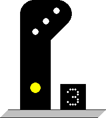 |
[6.52] Junction Indicator used with a Subsidiary Signal (e.g. three-lamp junction indicator with 'calling-on' disc).
Area: All Areas
Usage: High
Status: Obsolescent
|
[6.53] Junction Indication and Alphanumeric Route Indication displayed together (e.g. three-lamp junction indicator with theatre type route indicator).

Area: All Areas
Usage: Low
Status: Current
|
|
The LNER soon developed its own design of position light junction indicator, which had five white lights in each arm [6.54]. By 1939, the LMS was also installing position light junction indicators of the five-lamp type. Following nationalisation, this type was standard on all regions of British Railways apart from the Southern Region, which stuck with the three-lamp variety (see [6.50]).
|
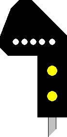 |
[6.54] Five-Lamp Junction Indicator (e.g. Position 2).

Area: LNER / LMS (subsequently All Areas)
Usage: High
Status: Current
|
|


